Gutor는 75년 이상의 검증된 경험으로 세계 최대의 산업용 UPS 시장 점유율을 가지고 있습니다. Gutor UPS 시스템은 석유 및 가스, 석유 화학, 화학, 원자력 산업 및 발전 산업과 같은 가장 까다로운 산업 환경에서 안전한 전력을 공급하도록 고객 맞춤 설계가 가능합니다.
Business
국내 UPS의 선두주자로 최적의 솔루션을 제공합니다.
UPS

Gutor PxW AC UPS System
작성자 관리자
날짜 2023-01-30 15:57:57
조회수 1430
PEW 5 – 200 kVA single phase; PDW 10 – 220 kVA three phase
Higher ratings on request
Higher ratings on request
- 지속적인 운영 프로세스 산업, 생산 시설 및 유틸리티 설비에서 제어, 모니터링 및 보호 기능을 수행하는 필수 장비에 대한 안전한 AC 전원 공급원인 온라인 UPS
- 사이리스터 제어 정류기와 IGBT-PWM 인버터를 갖춘 산업용 온라인 이중 변환 UPS 시스템
- Gutor PxW는 고객별 옵션과 맞춤형 설계가 가능하여 커스터마이징 된 산업용 UPS 또는 인버터를 찾는 고객에게 이상적인 제품임
- PEW 1000(1-phase output)
- PDW 3000(3-phase output)
Gutor PxW Technical Data
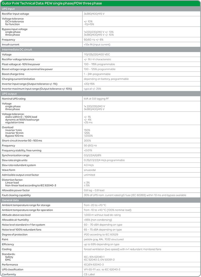
Gutor™ PxW Specifications
Typical single-line drawing

Battery voltage and UPS ratings

Standard configuration
- Single UPS
- UPS output voltage
- single phase: 1x230 V
- three phase: 3x400/230 V
- Rectifier input voltage: 3x400 V +10/-10%
- Bypass input voltage
single phase: 1x230 V +10/-10%
three phase: 3x400/230 V +10/-10% - Frequency: 50 Hz +/- 6%
- Six-pulse Rectifier with isolation transformer
- Rectifier sized for output PF = 0.8
- Rectifier input switch
- Fixed charging voltage IU characteristic
- Static switch EN Bypass (line power side) with additional backfeed protection
- LC display unit with additional alarm LEDs
- Alarm relays for battery operation and common alarm
- Bottom cable entry
- Ground terminal
- N+1 monitored two-speed fans
- Ambient temperature range from -10 to +40°C
- Protection IP20
- Painting pebble gray, RAL 7032 structured
- Battery MCCB optional in UPS
- Manual Bypass Switch three position in UPS
Options
- Parallel redundant configuration
- Other input voltages
three phase: 190 – 690 V - Other output voltages
single phase: 110 – 288 V
three phase: 190 – 690 V - Frequency 60 Hz +/- 6%
- 12-pulse Rectifier with isolation transformer
- Oversized rectifier
- Rectifier fuse
- Bypass input switch or MCCB
- Rectifier input MCCB
- Sensor for temperature dependent battery charging voltage, recommended for sealed batteries and wide temperature range
- Battery temperature alarm
- Diode for reverse polarity protection
- Rectifier output isolator/circuit breaker
- Battery fuse in UPS
- Battery fuse box
- Battery MCCB box
- Inverter input isolator/circuit breaker
- Oversized inverter
- Static Switch EA (Inverter side)
- Battery Monitor (programmable battery data)
- Battery asymmetry supervision
- AC and DC ground fault alarm
- RS-232/485 interface (event log download)
- RJ-45 Ethernet port for Web browser based monitoring
- RS-485 Modbus Protocol (slave)
- External time synchronization
- Top and/or bottom cable entry
- Space heaters
- Ventilation 100% redundant
- Panel lighting
- Ambient temperature maximum +55°C
- Allowable altitude up to 4,000 m above sea level
- Protection up to IP52
- Other colors
- Bypass isolation transformer
- Bypass stabilizer with isolation transformer
- Black start facility
- Key switch on front panel
- Additional analog meters 96x96, cl. 1.5
- Set with VM DC, AM Bat and output FM, VM, and AM
- Set with Input VM and AM with select switch
- kW of output
- Power factor
- Relay board A077, 16 fail-safe NO/NC contacts:
- Rectifier line power fault – Ground fault – DC Inverter fuse blown
- DC out of tolerance – 5x options – Bypass line power fault
- Rectifier fuse blown – Fan failure – Power supply unit fault
- Battery discharged – Overtemperature
- Relay board A078, 16 fail-safe NO/NC contacts:
- EA inhibited – Battery disconnected – Inverter ON
- EN inhibited – Battery – Boost charge operation
- Manual Bypass ON – Rectifier failure – Rectifier ON
- Asynchronous – EA ON – External horn
- Inverter fault – EN ON – Overload Inverter/Bypass
Additional options are available on request
Human-machine interface (front panel)

The front panel includes a comprehensive and flexible human-machine interface. It is divided into four sections:
- The system panel shows the system’s current state of operation (i.e., which part of the system is currently supplying the load and which is in stand-by mode). LEDs also indicate possible faults.
- Use the operations panel to turn the system on and off. The lamp-test button indicates whether all LED indication lights are functioning properly. To shut down the system, you have to press the ON and OFF buttons at the same time.
- Flexibly assign LEDs to indicate system alarms and external signals.
- On the alarm-indication panel, the respective LEDs light up to indicate a possible fault, or that an alarm has occurred.
Operational parameters
- Selectable second display language
- Bypass operation
- Boost charge
- Auto boost (charge)
- Battery-capacity test
- Battery-monitor test (optional)
- Set date/time
Measurements
- Load in percentage of nominal kVA rating
- AC rectifier line power 1 voltage and current
- AC bypass line power 2 voltage
- DC total current, battery voltage and current
- Battery temperature (with optional sensor)
- AC Inverter current
- AC output voltage, current and frequency
- AC output peak current
- Time left in battery operation with current load (optional with programmed battery data)
- Event log with date and time (operating mode changes and alarms)