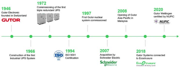
Gutor는 75년 이상의 검증된 경험으로 세계 최대의 산업용 UPS 시장 점유율을 가지고 있습니다. Gutor UPS 시스템은 석유 및 가스, 석유 화학, 화학, 원자력 산업 및 발전 산업과 같은 가장 까다로운 산업 환경에서 안전한 전력을 공급하도록 고객 맞춤 설계가 가능합니다.
Business
국내 UPS의 선두주자로 최적의 솔루션을 제공합니다.
UPS
Gutor PXP AC UPS System
작성자 관리자
날짜 2023-01-30 15:54:45
조회수 2396
PXP 1000 5 – 160 kVA single phase
PXP 3000 5 – 160 kVA three phase
PXP 3000 5 – 160 kVA three phase
- 대규모 설치 기반 및 다년간의 현장 신뢰도를 갖춘 플랫폼
- 신뢰성 향상을 위한 분산 제어 아키텍처
- 중복 및 개별 모니터링 팬
- 산업용 UPS 시스템 중 시장에서 가장 최소화된 설치 공간 필요
- 손실 및 냉각 요구사항을 줄이는 매우 우수한 효율성으로 비용 효율적
- 통합된 네트워크 관리 카드로 대부분의 프로토콜에 연결 가능
- PXP 1000(1-phase output)
- PXP 3000(3-phase output)
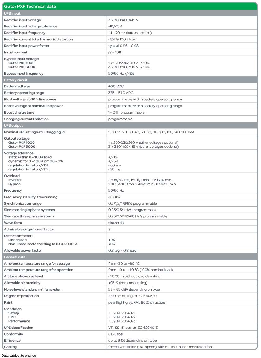
Gutor PXP Technical data
Gutor PXP Specifications
Typical single-line drawing

Standard configuration
- Static bypass switch EN
- Rectifier input switch
- Fixed charging voltage IU characteristic
- PFC rectifier (supplies 100% AC load @ 0.8 PF and charges battery with 20% of nominal power)
- Rectifier line power backfeed protection
- Battery-capacity test (full discharge with current load)
- Human-machine interface with additional LEDs for direct alarm display
- Ground terminal
- Bottom cable entry
- N+1 monitored two-speed fans
- Digital input
- Emergency power OFF (EPO)
- Two configurable inputs
- Digital (NO/NC relay)
- Common alarm
- Battery operation
- Static bypass switch On
Optional features – UPS input
- Other input voltages:
- 3 x 190, 208, 220, 230, 440, 460, 480, 500, 525, 600, 660, 690 V
- Rectifier input MCCB
- Without isolation transformer on rectifier line power ^T001
- Without isolation transformer on bypass line power ^T501
- Bypass stabilizer with isolation transformer
- Bypass mains backfeed protection
Optional features – Battery circuit
- Battery fuse in UPS
- Battery fuse box
- Battery MCCB in UPS
- Battery MCCB box (for non-hazardous areas or hazardous areas zone 1/2 Ex de IIC)
- Battery temperature alarm
- Battery monitor (programmable battery data)
- Battery asymmetry supervision
- Diode for reverse polarity protection
- Up to three sensors for temperature dependent battery charging voltage — recommended for valve regulated lead acid (VRLA) battery
Optional features – UPS output
- Other output voltages:
- 1 x 110, 115, 120, 127, 254, 265, 277 V
- 3 x 190, 200, 208, 220, 230, 440, 460, 480, 500, 525, 600, 660, 690 V
- Without isolation transformer on inverter output ^T002
- Analog meters 72 x 72mm or 96 x 96mm (directly beside of HMI):
- Rectifier mains (voltage, current, frequency)
- Bypass mains (voltage, current, frequency)
- Battery (voltage, current)
- Inverter output (voltage, current, frequency, PF, kVA, kW)
- Others on request built in distribution
- Digital outputs (NO/NC relay output):
- Operational indications
- Battery not connected
- Normal operation
- Static bypass operation
- Manual bypass operation
- Boost charge
- Float charge
- Inverter asynchronous
- Fail-safe alarms:
- Rectifier line power fault
- Bypass line power fault
- Battery discharged
- Fan failure
- Rectifier fault
- Inverter fault
- Static bypass switch fault
- Over temperature
- Battery ground fault
- More individual operation status indications or fail-safe alarms on request (maximum 19 relays in total)
Optional features – Communication
- Network management card (NMC) for Web browser based monitoring
- Modbus RS-485, IEC 61850
- Other interfaces are available on request
Optional features – Other alarms
- DC ground fault alarm
- AC ground fault alarm
Optional features – General
- Ambient temperature maximum +55°C
- Allowable altitude up to 4,000 m above sea level
- Air filters at air inlet
- Other colors
- Space heaters
- Panel lighting
- Top cable entry
- Protection up to IP52
- Cabinet height 2,300 mm (standard 1,900 mm) Additional options are available on request
Additional options are available on request
Human-machine interface (front panel)

The front panel includes a comprehensive and flexible human-machine interface. It is divided into three sections:
- Control and display consists of a liquid-crystal display screen, indication LEDs for operating modes, and pushbuttons to navigate through the display menus and control the UPS.
The user can access measurement data and system information via display menus, including the event and alarm logs. - Mimic diagram with multi-color LED indicates the current operational status of the system and its components. It clearly indicates the power path currently supplying the load and the availability of the other supplies.
- System alarms and external signals can be flexibly assigned to LEDs for visualization.
Settings accessible via display menu
- Auto start
- Auto boost charge
- Set date/time
- Charge mode
- Bypass operation
- Battery capacity test
- Battery monitor test (optional)
- Display settings
- Menu language
Measurements accessible via display menu
- AC rectifier line power input voltage, current, and frequency
- AC bypass line power input voltage, current, and frequency (optional)
- AC output voltage, current, and frequency
- Load in kVA, kW and percentage of nominal rating
- Battery voltage and current
- Battery capacitypercentage and expected runtime
- Total system status in parallel/redundant operation
- Three temperature measurements (with optional sensors)
- Runtime and switchover statistics
- Maximum and minimum voltages and currents
- Time-stamped event log (operation mode changes and alarms)